3D Shape Primitives API Reference
Contents
- OBJ_Generic3All
- OBJ_Generic3
- OBJ_Sphere
- OBJ_Cube
- OBJ_Cylinder
- OBJ_Line3
- OBJ_Cone
- OBJ_Prism
- OBJ_Revolve
- OBJ_Surface
OBJ_Generic3All
Properties
- light: 'directional' | 'point' | null = 'directional'
- copy: Array<CPY_Step | string> | CPY_Step
Create copies the shapes vertices to replicate the shape in space. Copies of normals, colors (if defined) and texture coordinates (if defined) will also be made.
- usage: TypeGLBufferUsage = 'STATIC'
use
'DYNAMIC'if the shape's vertices will be updated very frequently
OBJ_Generic3
Options object for a FigureElementPrimitive of a generic 3D shape. Extends OBJ_Generic3All and OBJ_FigurePrimitive
OBJ_GenericGL can be used for shape creation with custom shaders.
But for many custom shapes, only points and normals of the shape need to be defined, without needing to customize the shaders.
OBJ_Generic3 Provides the ability to create many custom shapes that don't need shader customization.
Properties
- glPrimitive: 'TRIANGLES' | 'POINTS' | 'FAN' | 'STRIP' | 'LINES' = 'TRIANGLES'
- points: Array<TypeParsablePoint>
positions of vertices of shape
- normals: Array<TypeParsablePoint>
normals for each vertex
- colors: Array<TypeColor>
define a color for each vertex if the shape will be more than just a single color. Otherwise use
colorif a single color. - texture: OBJ_Texture
use to overlay a texture onto the shape's surfaces
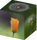
Cubes with texture on each face
figure.scene.setProjection({ style: 'orthographic' });
figure.scene.setCamera({ position: [1, 1, 2] });
figure.scene.setLight({ directional: [0.7, 0.5, 1] });
const [points, normals] = Fig.cube({ side: 0.8 });
figure.add({
make: 'generic3',
points,
normals,
texture: {
src: './flowers.jpeg',
coords: [
0, 0, 0.333, 0, 0.333, 0.5,
0, 0, 0.333, 0.5, 0, 0.5,
0.333, 0, 0.666, 0, 0.666, 0.5,
0.333, 0, 0.666, 0.5, 0.333, 0.5,
0.666, 0, 1, 0, 1, 0.5,
0.666, 0, 1, 0.5, 0.666, 0.5,
0, 0.5, 0.333, 1, 0, 1,
0, 0.5, 0.333, 0.5, 0.333, 1,
0.333, 0.5, 0.666, 1, 0.333, 1,
0.333, 0.5, 0.666, 0.5, 0.666, 1,
0.666, 0.5, 1, 1, 0.666, 1,
0.666, 0.5, 1, 0.5, 1, 1,
],
loadColor: [0, 0, 0, 0],
},
});
Create a a ring around a sphere.
figure.scene.setProjection({ style: 'orthographic' });
figure.scene.setCamera({ position: [1, 1, 2] });
figure.scene.setLight({ directional: [0.7, 0.5, 1] });
const { sphere, polygon, revolve } = Fig;
const [spherePoints, sphereNormals] = sphere({ radius: 0.15 });
// The ring is a flattened doughnut
const [ringPoints, ringNormals] = revolve({
profile: polygon({
close: true,
sides: 20,
radius: 0.05,
center: [0, 0.3],
direction: -1,
transform: ['s', 0.1, 1, 1],
}),
normals: 'curve',
sides: 50,
transform: ['d', 0, 1, 0],
});
const a = figure.add({
make: 'generic3',
points: [...spherePoints, ...ringPoints],
normals: [...sphereNormals, ...ringNormals],
color: [1, 0, 0, 1],
transform: [['r', 0.15, 1, 0, 0], ['r', 0.3, 0, 1, 0]],
});
// Animate the shape to slowly rotate around the x and y axes
a.animations.new()
.custom({
callback: (t) => {
a.transform.updateRotation(t * 0.15);
a.transform.updateRotation(t * 0.3, null, 1);
},
duration: null,
})
.start();
To test examples, append them to the boilerplate
OBJ_Sphere
Sphere shape options object that extends OBJ_Generic3All and OBJ_FigurePrimitive
By default, a sphere with its center at the origin will be created.
Properties
- sides: number = 10
number of sides around sphere's half great circle
- radius: number = 1
radius of sphere
- normals: 'curve' | 'flat' = flat
flatnormals will make light shading across a face cone constant.curvewill gradiate the shading. Usecurveto make a surface look more round with fewer number of sides. - center: TypeParsablePoint = [0, 0]
center position of sphere
- lines: boolean
if
truethen points representing the edes of the faces will be returned. Iffalse, then points representing two triangles per face and an associated normal for each point will be returned.
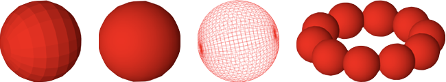
Example 1
figure.add({
make: 'sphere',
radius: 0.5,
color: [1, 0, 0, 1],
});
Sphere with 'curve' normals
figure.add({
make: 'sphere',
radius: 0.5,
normals: 'curve',
color: [1, 0, 0, 1],
});
Wire mesh sphere
figure.add({
make: 'sphere',
radius: 0.5,
sides: 30,
lines: true,
normals: 'curve',
color: [1, 0, 0, 1],
});
Ring of spheres, rotated to by in xz plane
figure.add({
make: 'sphere',
radius: 0.1,
color: [1, 0, 0, 1],
center: [0.3, 0, 0],
normals: 'curve',
copy: [
{ along: 'rotation', num: 10, step: Math.PI * 2 / 10 },
],
transform: ['r', Math.PI / 2, 1, 0, 0],
});
To test examples, append them to the boilerplate
OBJ_Cube
Cube shape options object that extends OBJ_Generic3All and OBJ_FigurePrimitive
By default, a cube will be constructed around the origin, with the xyz axes being normal to the cube faces.
Properties
- side: number = 1
side length
- center: TypeParsablePoint
center point (
[0, 0]) points of cube - lines: boolean = false
if
truethen points representing the 12 edges of the cube will be returned. Iffalse, then points representing two triangles per face (12 triangles, 36 points) and an associated normal for each point will be returned.
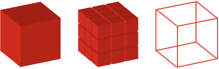
Example 1
figure.add({
make: 'cube',
side: 0.5,
color: [1, 0, 0, 1],
});
3x3 grid of cubes
figure.add({
make: 'cube',
side: 0.2,
color: [1, 0, 0, 1],
copy: [
{ along: 'x', num: 2, step: 0.22 },
{ along: 'y', num: 2, step: 0.22 },
{ along: 'z', num: 2, step: 0.22 },
],
});
Wire mesh cube
figure.add({
make: 'cube',
side: 0.5,
lines: true,
color: [1, 0, 0, 1],
});
To test examples, append them to the boilerplate
OBJ_Cylinder
Cylinder shape options object that extends OBJ_Generic3All and OBJ_FigurePrimitive
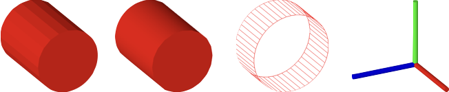
By default, a cylinder along the x axis will be created.
Properties
- sides: number = 10
number of cylinder sides
- radius: number = 1
radius of cylinder
- normals: 'curve' | 'flat' = flat
flatnormals will make shading (from light source) across a face cone constant.curvewill gradiate the shading. Usecurveto make a surface look more round with fewer number of sides. - line: TypeParsableLine
line that can position and orient the cylinder. First point of line is cylinder base center, and second point is the top center.
- length: number = 1
length of the cylinder if
lineisn't defined - ends: boolean | 1 | 2 = true
truefills both ends of the cylinder.falsedoes not fill ends.1fills only the first end.2fills only the the second end. - rotation: number
rotation of base - this is only noticable for small numbers of sides (
0) points of cube - lines: boolean
if
truethen points representing the edes of the faces will be returned. Iffalse, then points representing two triangles per face and an associated normal for each point will be returned.
Example 1
figure.add({
make: 'cylinder',
radius: 0.2,
length: 0.5,
sides: 20,
color: [1, 0, 0, 1],
});
Use curve normals to give rounder looks for same number of sides
figure.add({
make: 'cylinder',
radius: 0.2,
length: 0.5,
sides: 20,
normals: 'curve',
color: [1, 0, 0, 1],
});
Wire mesh cylinder
figure.add({
make: 'cylinder',
radius: 0.2,
length: 0.2,
lines: true,
sides: 50,
ends: false,
color: [1, 0, 0, 1],
});
Three cylinders as x, y, z axes
figure.add([
{
make: 'cylinder',
radius: 0.02,
line: [[0, 0, 0], [0.5, 0, 0]],
color: [1, 0, 0, 1],
},
{
make: 'cylinder',
radius: 0.02,
line: [[0, 0, 0], [0, 0.5, 0]],
color: [0, 1, 0, 1],
},
{
make: 'cylinder',
radius: 0.02,
line: [[0, 0, 0], [0, 0, 0.5]],
color: [0, 0, 1, 1],
},
]);
To test examples, append them to the boilerplate
OBJ_Line3
3D Line options object that extends OBJ_Generic3All and OBJ_FigurePrimitive
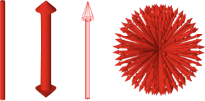
A 3D line is a cylinder with optional arrows on the end. Unlike a 2D line, the arrow profiles can only be simple triangles.
Properties
- p1: TypeParsablePoint = [0, 0, 0]
- p2: TypeParsablePoint = default: p1 + [1, 0, 0]
- width: number
width of line
- arrow: OBJ_Line3Arrow | boolean
define to use arrows at one or both ends of the line
- sides: number = 10
number of sides
- normals: 'curve' | 'flat' = curve
flatnormals will make light shading across a line face constant.curvewill gradiate the shading. Usecurveto make a surface look more round with fewer number of sides. - rotation: number = 0
rotation of line around its axis - this is only noticable for small numbers of sides
- lines: boolean
if
truethen points representing the edes of the faces will be returned. Iffalse, then points representing two triangles per face and an associated normal for each point will be returned.
Simple line
figure.add({
make: 'line3',
p1: [0, 0, 0],
p2: [0, 1, 0],
color: [1, 0, 0, 1],
});
Thick line with arrows on both ends
figure.add({
make: 'line3',
p1: [0, 0, 0],
p2: [0, 1, 0],
arrow: { ends: 'all', width: 0.1, length: 0.1 },
sides: 30,
width: 0.05,
color: [1, 0, 0, 1],
});
Wire mesh line with arrow
figure.add({
make: 'line3',
p1: [0, 0, 0],
p2: [0, 1, 0],
arrow: { ends: 'end' },
color: [1, 0, 0, 1],
lines: true,
});
Ball of arrows
figure.add(
{
make: 'line3',
p1: [0, 0, 0],
p2: [0, 0.4, 0],
color: [1, 0, 0, 1],
width: 0.01,
arrow: { end: 'end', width: 0.02 },
copy: [
{ along: 'rotation', num: 20, step: Math.PI * 2 / 20 },
{ along: 'rotation', axis: [0, 1, 0], num: 20, step: Math.PI * 2 / 20 },
],
},
);
To test examples, append them to the boilerplate
OBJ_Cone
Cone shape options object that extends OBJ_Generic3All and OBJ_FigurePrimitive
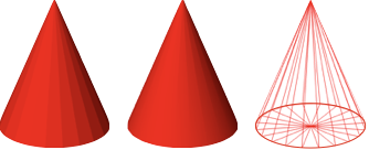
By default, a cone with its base at the origin and its tip along the x axis will be created.
Properties
- sides: number = 10
number of sides
- radius: number
radius of cube base
- normals: 'curve' | 'flat' = flat
flatnormals will make light shading across a face cone constant.curvewill gradiate the shading. Usecurveto make a surface look more round with fewer number of sides. - line: TypeParsableLine
line that can position and orient the cone. First point of line is cone base center, and second point is cone tip.
- length: number = 1
length of the cone along the x axis if
lineisn't defined - rotation: number
rotation of base - this is only noticable for small numbers of sides (
0) points of cube - lines: boolean
if
truethen points representing the edes of the faces will be returned. Iffalse, then points representing two triangles per face and an associated normal for each point will be returned.
Example 1
figure.add({
make: 'cone',
radius: 0.2,
sides: 20,
color: [1, 0, 0, 1],
line: [[0, 0, 0], [0, 0.5, 0]],
});
Cone with curve normals
figure.add({
make: 'cone',
radius: 0.2,
normals: 'curve',
sides: 20,
color: [1, 0, 0, 1],
line: [[0, 0, 0], [0, 0.5, 0]],
});
Wire mesh cone
figure.add({
make: 'cone',
radius: 0.2,
normals: 'curve',
sides: 20,
color: [1, 0, 0, 1],
line: [[0, 0, 0], [0, 0.5, 0]],
lines: true,
});
To test examples, append them to the boilerplate
OBJ_Prism
Prism shape options object that extends OBJ_Generic3All and OBJ_FigurePrimitive
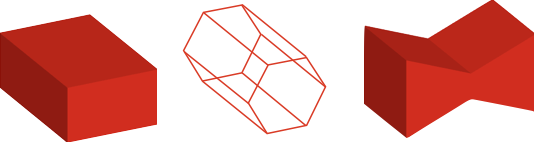
A prism base is defined in the XY plane, and it's length extends
into +z. Use transform to orient it in any other way.
Triangles will be created for the ends if the base is convex. If the base
is not convex, use baseTriangles to define the triangles.
Properties
- base: number
base border points defined in the XY plane - the points should be defined in the counter-clock-wise direction.
- baseTriangles: Array<TypeParsablePoint>
triangles in the XY plane that create the base fill. If the base is convex, then the triangles can be auto-generated and this property left undefined.
- length: number
length of the prism
- lines: boolean = false
if
truethen points representing the edges of the prism will be returned. Iffalse, then points representing triangle faces and associated normals will be returned.
Create a rectangular prism
figure.add(
{
make: 'prism',
base: [[0, 0], [0.5, 0], [0.5, 0.2], [0, 0.2]],
color: [1, 0, 0, 1],
},
);
Create a hexagonal prism along the x axis with lines
figure.add(
{
make: 'prism',
base: Fig.polygon({ radius: 0.1, sides: 6 }),
color: [1, 0, 0, 1],
transform: ['r', Math.PI / 2, 0, 1, 0],
lines: true,
},
);
Create a bow tie prism defining the base triangles
figure.add(
{
make: 'prism',
base: [[0, 0], [0.25, 0.1], [0.5, 0], [0.5, 0.3], [0.25, 0.2], [0, 0.3]],
baseTriangles: [
[0, 0], [0.25, 0.1], [0.25, 0.2],
[0, 0], [0.25, 0.2], [0, 0.3],
[0.25, 0.1], [0.5, 0], [0.5, 0.3],
[0.25, 0.1], [0.5, 0.3], [0.25, 0.2],
],
color: [1, 0, 0, 1],
transform: ['r', Math.PI / 2, 0, 1, 0],
},
);
To test examples, append them to the boilerplate
OBJ_Revolve
Revolve shape options object that extends OBJ_Generic3All and OBJ_FigurePrimitive.
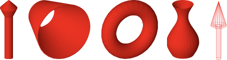
Revolve (or radially sweep) a profile in the XY plane around the x axis to form a 3D surface. The profile y values must be greater than or equal to 0.
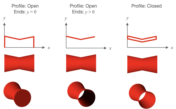
Profiles can be open (start and end point are different) or closed (start and end point are equal).
For predictable lighting results, profiles should be created with the following rules:
- An open profile's start points should have an x value less than its end point
- Closed profiles where all points have y > 0 should be defined in the clockwise direction when looking at the XY plane from the +z axis.
If an open profile's start and ends points are at y = 0, then the final shape will look solid.
If an open profile's start and/or ends points have y > 0, then the final shape will look like a surface open at the ends with y > 0. As a surface can have only one color, then looking inside the shape the surface lighting will be opposite to that expected. To create open ended solids with lighting that is as expected, create the outside and inside surface with a closed profile.
Properties
- profile: Array<TypeParsablePoint>
XY plane profile to be radially swept around the x axis
- sides: number
number of sides in the radial sweep
- normals: 'flat' | 'curveRows' | 'curveRadial' | 'curve'
flatnormals will make shading (from a light source) across a face of the object a constant color.curveProfilewill gradiate the shading along the profile.curveRadialwill gradiate the shading around the radial sweep.curvewill gradiate the shading both around the radial sweep and along the profile. Usecurve,curveProfile, orcurveRadialto make a surface look more round with fewer number of sides. - rotation: number
by default the profile will start in the XY plane and sweep around the x axis following the right hand rule. Use
rotationto start the sweep at some angle where 0º is in the XY for +y and 90º is in the XZ plane for +z. initial angle of the revolve rotation - axis: TypeParsablePoint
orient the draw space vertices of the shape so its axis is along this vector
- lines: boolean
if
truethen points representing the edes of the faces will be returned. Iffalse, then points representing two triangles per face and an associated normal for each point will be returned.
Example 1
figure.add({
make: 'revolve',
profile: [[0, 0], [0, 0.05], [0.5, 0.05], [0.6, 0.1], [0.7, 0]],
axis: [0, 1, 0],
color: [1, 0, 0, 1],
sides: 20,
});
If creating a shell, then also create the inside surface as this will make
// lighting more correct (note there is not shaddows).
// Ensure to close the shell by adding the first point to the end of the
// profile
figure.add({
make: 'revolve',
profile: [[0, 0.15], [0.5, 0.3], [0.5, 0.29], [0, 0.14], [0, 0.15]],
color: [1, 0, 0, 1],
sides: 30,
normals: 'curveRadial',
});
Curvy vase like shape
const x = Fig.range(0, 0.5, 0.01);
const profile = x.map(_x => [_x, 0.1 + 0.05 * Math.sin(_x * 2 * Math.PI * 2)]);
figure.add({
make: 'revolve',
profile: [...profile, [0.4, 0], [0, 0], [0, 0.1]],
axis: [0, 1, 0],
color: [1, 0, 0, 1],
sides: 30,
});
Make a torus by revolving a polygon around the axis. As the polygon is above
// the x axis, a hole will be created
// Try using `normals: 'curve'`, `normals: 'curveProfile'`, and
// `normals: 'curveRadial'` to see different curve options.
const { polygon } = Fig;
figure.add({
make: 'revolve',
profile: polygon({
radius: 0.1, center: [0, 0.3], sides: 20, direction: -1, close: true,
}),
color: [1, 0, 0, 1],
sides: 30,
});
Wire mesh arrow
figure.add({
make: 'revolve',
profile: [[0, 0.03], [0.4, 0.03], [0.4, 0.09], [0.7, 0]],
axis: [0, 1, 0],
color: [1, 0, 0, 1],
sides: 20,
lines: true,
});
Open profile y = 0 at ends
figure.add({
make: 'revolve',
profile: [[0, 0], [0, 0.3], [0.5, 0.2], [1, 0.3], [1, 0]],
color: [1, 0, 0, 1],
sides: 30,
});
Open profile y > 0 at ends
figure.add({
make: 'revolve',
profile: [[0, 0.3], [0.5, 0.2], [1, 0.3]],
color: [1, 0, 0, 1],
sides: 30,
});
Closed Profile
figure.add({
make: 'revolve',
profile: [[0, 0.3], [0.5, 0.2], [1, 0.3], [1, 0.29], [0.5, 0.19], [0, 0.29], [0, 0.3]],
color: [1, 0, 0, 1],
sides: 30,
});
To test examples, append them to the boilerplate
OBJ_Surface
Surface shape options object that extends OBJ_Generic3All and OBJ_FigurePrimitive.
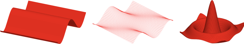

A surface is defined with a 2D matrix of points. Triangles that fill the surface are created between neighboring points in the matrix.
If a surface is defined with 9 points (an array or arrays in JavaScript):
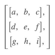
Then triangles will be created between adb, deb, bec, efc, dge,
ghe, ehf, and hif.
The normal for triangle 'adb' is in the direction of the cross product
of vector 'ad' with vector 'ab' (use the right hand rule where the fingers
of the right hand curl from vector 'ad' to 'ab', and the thumb will then be
the direction of the normal). Similarly, the normal of hif will be the
direction of the cross product of hi with hf.
Use the property invertNormals to make all the normals go in the reverse
direction.
A surface can be open or closed at the end rows or columns of the matrix. For example, a surface has closed columns if the first and last column of the matrix have identical points. A surface is has open rows if the first and last row of the matrix have different points.
If using curved normals ('curve', 'curveRows' or 'curveColumns') with
closed surfaces, use closeRows or closeColumns to ensure normal
curvature is maintained at the end rows
and columns.
Properties
- points: Array<Array<TypeParsablePoint>>
A grid of points that define a 3D surface
- normals: 'curveColumns' | 'curveRows' | 'curve' | 'flat'
flatnormals will make shading (from a light source) across a face of the object a constant color.curveRowswill gradiate the shading along the rows of the grid.curveColumnswill gradiate the shading along the columns of the grid.curvewill gradiate the shading along both rows and columns. Usecurve,curveRows, orcurveColumnsto make a surface look more round with fewer number of sides. - closeRows: boolean = false
Set to
trueif first row and last row are the same, and normals is'curveRows'or'curve'to get correct normal calculations - closeColumns: boolean
Set to
trueif first row and last column are the same, and normals is'curveColumns'or'curve'to get correct normal calculations (false) shape - lines: boolean
if
truethen points representing the edes of the faces will be returned. Iffalse, then points representing two triangles per face and an associated normal for each point will be returned. - invertNormals: boolean
if
truethen all normals will be inverted
Example 1
const points = Fig.surfaceGrid({
x: [-0.8, 0.7, 0.03],
y: [-0.8, 0.7, 0.03],
z: x => 0.2 * Math.cos(x * 2 * Math.PI),
});
figure.scene.setCamera({ up: [0, 0, 1] });
figure.add({
make: 'surface',
points,
color: [1, 0, 0, 1],
});
Surface wire mesh
const points = Fig.surfaceGrid({
x: [-0.8, 0.8, 0.03],
y: [-0.8, 0.8, 0.03],
z: (x, y) => y * 0.2 * Math.cos(x * 2 * Math.PI),
});
figure.scene.setCamera({ position: [-1, -1, 0.7], up: [0, 0, 1] });
figure.add({
make: 'surface',
points,
lines: true,
color: [1, 0, 0, 1],
});
Surface with wire mesh and fill
const points = Fig.surfaceGrid({
x: [-0.8, 0.8, 0.03],
y: [-0.8, 0.8, 0.03],
z: (x, y) => {
const r = Math.sqrt(x * x + y * y) * Math.PI * 2 * 2;
return Math.sin(r) / r;
},
});
// Orient the camera so z is up
figure.scene.setCamera({ up: [0, 0, 1] });
figure.add({
make: 'surface',
points,
color: [1, 0, 0, 1],
});
figure.add({
make: 'surface',
points,
lines: true,
color: [0, 0, 0, 1],
});
Simple Closed surface around the x axis
figure.add({
make: 'surface',
normals: 'curveColumns',
closeRows: true,
points: [
[[0, 0, 0.5], [1, 0, 0.5]],
[[0, -0.5, 0], [1, -0.5, 0]],
[[0, 0, -0.5], [1, 0, -0.5]],
[[0, 0.5, 0], [1, 0.5, 0]],
[[0, 0, 0.5], [1, 0, 0.5]],
],
color: [1, 0, 0, 1],
});
Simple Closed surface around the x axis with curved normals
figure.add({
make: 'surface',
normals: 'curveColumns',
closeRows: true,
points: [
[[0, 0, 0.5], [1, 0, 0.5]],
[[0, -0.5, 0], [1, -0.5, 0]],
[[0, 0, -0.5], [1, 0, -0.5]],
[[0, 0.5, 0], [1, 0.5, 0]],
[[0, 0, 0.5], [1, 0, 0.5]],
],
color: [1, 0, 0, 1],
});
Create a matrix of points by taking a profile in XY and rotating
// it around the x axis
const { Point, Transform } = Fig;
const points = [];
// Rotation step
const dr = Math.PI * 2 / 50;
for (let r = 0; r < Math.PI * 2 + dr / 2; r += dr) {
// Rotation matrix of rotation step around x axis
const m = new Transform().rotate(r, 1, 0, 0).matrix();
// A row of points is a profile rotated by some amount r
points.push([]);
// Make a profile for x values from 0 to 1
for (let x = 0; x < 1; x += 0.05) {
// The y coordinate of the profile changes with both x value, and
// rotation value
const y = 0.1 * Math.sin(6 * x) + 0.25 + 0.1 * Math.cos(3 * r);
const p = new Point(x, y).transformBy(m);
points[points.length - 1].push(p);
}
}
figure.add({
make: 'surface',
points,
color: [1, 0, 0, 1],
});
To test examples, append them to the boilerplate
the scene light that will be cast on the shape. Use
nullfor no lighting - all surfaces will have the defined color.